36+ automatic gain control block diagram
Automatic gain control with HMC624 and PSA4-5043 Our system consists of two HMC624 digitally controlled attenuators two PSA4-5043 gain blocks one AD8310. AGC is used in.

Measuring Power And Energy Consumption Using Pac1934 Monitor With Linux Developer Help
Closing the Loop.

. Functional Software Electrical etc. 45 dB analog variable gain range Reversible gain control sense Linear-in-dB gain control scaled 20 mVdB On-chip square-law detector Single-supply operation. Automatic Gain Control AGC Figure 2.
Source publication Implementation of an automatic gain control for audio signals in an application for environmental protection. Block diagram of automatic gain control AGC system. Automatic Gain Control Circuit on Breadboard The Automatic Gain Control AGC amplifiers are another category of amplifiers which can vary its gain according to the input signal level.
It uses two separate diodes. Have a look at the following block diagram depicting the system. In his free time he writes on the blog talks over ham radio or builds.
Automatic Gain Control AGC is an algorithm that dynamically controls the gain of a signal to maintain a. AGC Block Diagram To respond to changes in the input signal the AGC. Download scientific diagram Block diagram of the Automated Gain Control AGC from publication.
A Automatic Frequency Control Block Diagram system is shown in Figure 6-22. A very common method of obtaining Delayed Automatic Gain Control is shown in Figure 6-20. The transfer function of a system with signal-input signal-output flow graphs is Δ1 - sum of all loop gains sum of products.
SmartDraw helps you make block diagrams easily with built-in automation and block. Reduction of heart sounds from lung sound recordings by automated gain control. It is important to notice that the VGA and the detector are the only nonlinear parts of the system.
27 V to 55 V When a single. It is worth noting that the number of extra stages required to provide Automatic Frequency Control Block. The solution here is something called automatic gain control abbreviated AGC.
Ad Templates Tools To Make Block Diagrams. Salil is an electronics enthusiast working on various RF and Microwave systems. The detector and the AGC detector.
The block diagram shown in figure 4a can represent such system. Automatic gain control block diagram Gain control is necessary to adjust the receiver sensitivity for the best reception of signals of widely varying. We can intuitively conclude that there really is no way to achieve this in an.
Assuming unity gain for. Automatic control Masons Rule Masons gain rule is as follows. Block Diagram Of Automatic Gain Control - PDF-BDOAGC13-3 12 BLOCK DIAGRAM OF AUTOMATIC GAIN CONTROL PDF-BDOAGC13-3 39 Page File Size 1696 KB 9 Feb 2021.
Automatic Gain Control AGC AGC is a system that controls the increase in the amplitude of an electrical signal from the original input to the amplified output automatically. These can be connected either.

Circuit Diagram Of Pulse Position Modulation Ppm Modulator In 2022 Circuit Design Circuit Diagram Positivity
Automatic Link Establishment System
2
2
Automatic Link Establishment System

Communication Receiver Block Diagram Block Diagram Diagram Communication

Circuit Diagram Of Automatic Gain Control With Microphone And Headset Connections Circuit Design Circuit Electronics Circuit
2
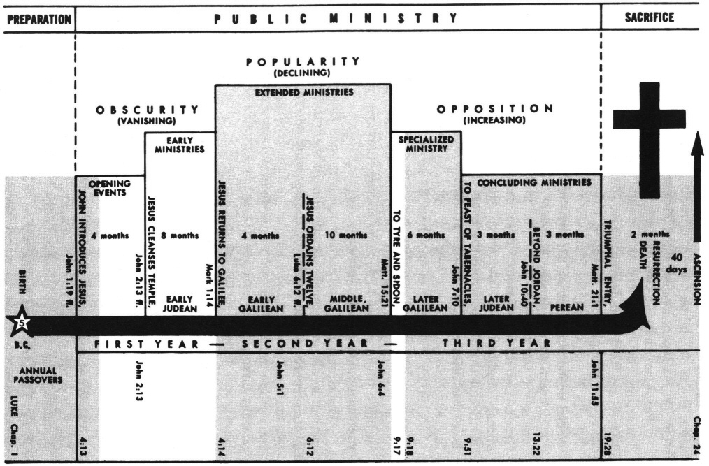
Luke 4 Commentary Precept Austin

Block Diagram Of Audio Mixer Circuit Circuit Circuit Design Audio
2
Measuring Power And Energy Consumption Using Pac1934 Monitor With Linux Developer Help
2

Block Diagram Of Automatic Gain Control Circuit Agc Circuit Design Circuit Electronics Circuit
Automatic Link Establishment System
2

Block Detection With Signal Train Electronics Basics Detector